- October 26, 2023
- Posted by: Dyaneshwar Nirmale
- Category: Uncategorized

A Current Transformer (CT) is an instrument transformer that is used to measure alternating electric currents. It’s primarily used in electricity metering, protective relaying and the monitoring of the electrical power industry.
What is a Current Transformer?
A current transformer (CT) is an electrical device used to measure the electric current in a circuit. It’s a type of instrument increases the resistance in transformer current in its secondary winding that is proportional to the current flowing in its primary winding. The primary winding of a current transformer is typically a single turn of a conductor or a bus bar through which the current to be measured flows.
How CT Works:
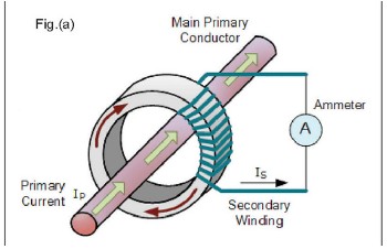
The Current Transformer (C.T.), categorized as an “instrument transformer,” generates an alternating current within its secondary winding. This CT generated current is directly proportional to the current under measurement in its primary circuit. Current transformers operate on the principle of electromagnetic induction, which was first discovered by Michael Faraday. Here’s how CT works:
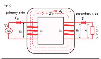
When current flows through primary, as per Faraday’s law of Electricity, it induces primary flux Ø 1 into the core which results in secondary current I2. This current I2 also induces secondary flux Ø 2 but in opposite direction. Hence it opposes the primary flux Ø 1.
Therefore, it is called as counter balancing flux. This resultant flux
Ø = Ø 1 – Ø 2 is the flux that flows through the core. Its value is relatively small compared to Ø 1. This flux maintains linear relationship between I secondary and I primary depending on the core material (shown In fig.(b)). check out more about current transformer & how CT works.
-
Coil and Core Design of Current Transformer (CT):
A CT consists of a primary winding, a secondary winding and a magnetic core. Connect the primary winding in series with the circuit through which you need to measure the current.
-
Mutual Inductance:
When an alternating current flows through the primary winding, it generates a magnetic field in the core. This magnetic field then induces a current in the secondary winding through mutual inductance.
-
Step-Down Ratio:
The number of turns in the secondary winding is significantly greater than in the primary winding. This difference in turns (N2/N1) creates a step-down ratio, which allows the CT to reduce the current to a manageable level for measurement.
-
CT Isolation:
The CT provides electrical isolation between the primary circuit (the high-voltage side) and the secondary circuit (the low-voltage side). This isolation protects the measuring instruments and operators from the high currents in the primary circuit.
-
CT Measurement:
The reduced current in the secondary winding proportionally reflects the primary current and can drive various devices such as ammeters, watt-hour meters, protective relays, or other control devices.
Current transformers are indispensable devices in the electrical power industry, enabling accurate measurement, monitoring and protection of electrical currents. Their working principle, design and applications make them vital for electricity metering, protective relaying, and power management. By using current transformers, electrical systems can operate efficiently, ensuring the safety of equipment and personnel. Newtek Electrical, a leading manufacturer of current transformers, potential transformers, and digital meters, offers high-quality CTs fabricated with Nylon and Resin cast for added protection. With their commitment to technological advancements, they consistently deliver premium quality products to meet industry standards.