- May 9, 2021
- Posted by: Dyaneshwar Nirmale
- Category: Digital Meters
Introduction:
Relay outputs in MFM/VAF meters are inbuilt changeover contacts that change the state of contacts based on the present condition (Less than or Greater than) for a particular measured parameter in the meter.
MFM/VAF meters have generally one or two optional relay outputs. The relay outputs can be programmed independently either as limit switch or pulse output (only for MFM). This section elaborates on relay output programmed as limit switch.
What is a Limit Switch?
A limit switch is nothing but a set point trip relay output. A set point trips relay output if the input exceeds a user defined hi/lo set point limit. This enables controlling the operation by meter based on measurements.
Consider the following parameters in the meter for a limit switch:
Consider the following parameters in the meter for a limit switch:
1) Measured parameter to be monitored.
2) Trip point
3) Hysteresis
4) condition for tripping ( > or <) and Relay status after tripping
5) Energizing delay/De-energizing delay required before tripping.
Example: Consider a 3 phase induction motor of 415VLL, 5A,
3.5kKW which is to be protected from overvoltage/overcurrent. Here, we need a mechanism to automatically cut off the motor’s power supply when the input voltage exceeds 5O0V or input current exceeds 5A, and restores the supply when the voltage/current are back to normal. This is achieved by programing the Meter for relay output:
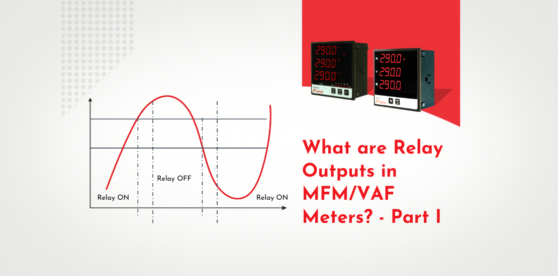
RELAY 1: Measured parameter: VLL Trip point (Limit A) = 500VLL Hysterisis = 10% of Trip point= 50V. Limit B = 500V-50V = 450V Condition: Hi-Alarm —De-Energized (> 500VLL – relay should be OFF) Energizing delay: 2 sec De-Energizing delay: 2sec
(Refer Fig 1 and Fig 2)
RELAY 2: Measured parameter: A Trip point (Limit A) = 5A
Hystetisis = 10% of Trip point = 0.5A. Limit B = 5A-0.5A = 4.5A Condition: Hi-Alarm —De-Energized (> 5A – relay should be OFF) Energizing delay: 2sec De-Energizing delay: 2sec
Fig 1 and Fig 2 illustrate the operation of RELAY 1. The relay is ON when Vi< A (500V). WhenVi crosses 500V, due to deenergizing delay of 2 sec, RELAY 1 trips after 2 secs. The relay remains OFF until Vi is above 450V (Limit B). When Vi < B (450V), the relay turns ON again after 2 sec due to energizing delay. Thus, the supply to 3 Phase motor is automatically cut off and then restored based on the input conditions and the user defined set-points in the Meter.
HYSTERISIS is the noise margin that prevents chattering/hunting of relay outputs. This happens when the input fluctuates around Trip point due to noise.
Energizing/De-energizing delay eliminates false tripping in case the input exceeds trip point due to noise spikes in the input waveform. Meter confirms twice (just before delay and after delay) whether the input is really above the Trip point before tripping the relay.
It will not trip if the input is found above the trip point only once.
This eliminates false tripping. The protection offered by the limit switch is not restricted to voltage or current.
The user may get protection for over or under for any parameter (like Power, Frequency, Demand, Maximum Demand). When relay output is programmed as limit switch for Max Power Demand, the Meter works as a Demand Controller which cuts off the load automatically when Max Power demand is exceeded.
")
Conclusion
The limit switch in an electrical setup serves the dual purpose of protection and control in power consumption. By using the limit switch as a demand controller, you could significantly reduce power consumption and save costs.
