- April 26, 2022
- Posted by: Dyaneshwar Nirmale
- Categories: Business plans, Digital Meters
Current transformers use a simple mechanism for stepping down the power from utility lines. The CT uses just two components- core and windings to do this job. However, if this is to be done efficiently, a high build quality, proper testing, and the use of the right materials in the current transformer is vital..
We have discussed the materials used for the current transformer core here. The present article elaborates on the construction of current transformer windings.
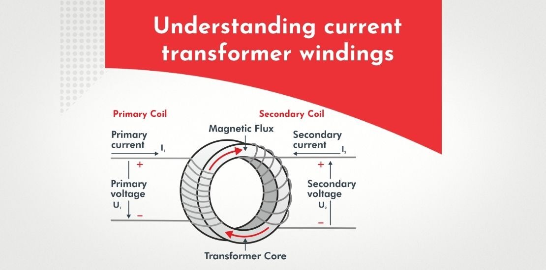
Construction of current transformer windings
The current transformer has two sets of windings. It receives the high-voltage direct current from the utility line in its primary winding and generates an alternate current in its secondary winding. The primary and secondary windings are wound upon an iron core. While the primary winding is connected in series with the load, the secondary winding is connected to measuring devices.
As opposed to the power transformer or voltage transformer, the primary winding of a current transformer has just one or very few turns. The primary winding of the current transformer could be either a single flat turn, a coil of heavy-duty wire wrapped around the core, or a conductor or bus bar passing through the central hole.
The secondary winding might have more number of turns. The core of the CT has a larger cross-sectional area so that a smaller cross-sectional area wire could be used to create a low magnetic flux density depending on how much the current needs to be stepped down.
The amount of current flowing through the high-powered lines into the primary winding determines the number of turns the secondary winding will have. The more the current flow, the more the number of turns.
Materials used for current transformer windings
Copper and aluminum are used as primary materials for current transformer windings. Aluminum is more lightweight and costs less than copper. However, a larger cross-section of the aluminum conductor must be used to carry the same amount of current as a copper conductor.
The copper conductor on the other hand offers better mechanical strength, better resistance to heat, and higher conductivity. Newtek Current Transformers use high-quality copper windings to ensure efficient performance.
If the working conditions involve extreme forces, materials such as silver-bearing copper could be used for the winding.
Resistance in current transformer windings
A smooth-flowing electrical current takes the path of least resistance. If resistance is present in the current transformer winding, it could lead to loss and reduce the efficiency of the current transformer. The winding resistance in the current transformer could change over time due to factors such as the age of the transformer, load, working conditions, and use of the current transformer.
To ensure the lowest possible winding resistance, all current transformers must undergo winding resistance tests The winding resistance is calculated by dividing the voltage drop across the windings with the DC current applied through the windings
The current transformer must be demagnetized using a saturation test after the winding resistance test is completed.