- June 19, 2021
- Posted by: Dyaneshwar Nirmale
- Category: Digital Meters
Installing multifunction meters involves multitude of simple tasks. However, despite their simplicity, if any of these tasks are ignored or if they escape our attention, it could result in wrong readings, and have deep impact on entire cost-saving strategy. In this checklist, we look at such tiny but critical steps and consideration in installing multifunction meters for a metering project
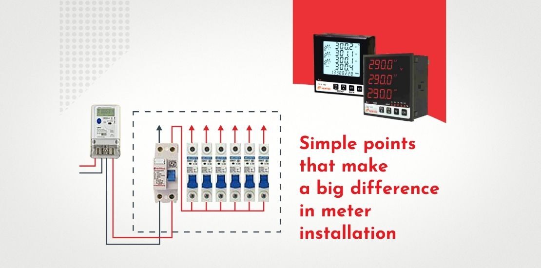
Placement and wiring
Steps to take
- Place the meter inside an electrical panel
- Provide additional enclosure for added protection
- Connect the current transformer & potential transformer to the meter as per your application.
Points to ponder
- Which type of connection you need to do ?
- Which rating of CT & PT depending on your application?
-In case the CT isn’t compatible, choose a compatible CT model
Connecting the meter to load voltage
Steps to take
- Ensure that all the MCB’s, LCB’s or Breakers OFF before making connections to meter
- Wire lugs recommended for voltage & current connections. Loose connections are not allowed.
- Specially for current because if CT secondary opened there chances of CT damage/Explosion/burning
Points to ponder
- Wear adequate safety gear and follow safety protocol
- The meter’s voltage input should be connected to a to a dedicated circuit breaker which is fed by the same voltage source as the load.
- If a dedicated circuit breaker is not available, pick an easily accessible circuit breaker connected to the same voltage source as the load.
Newtek meters are enabled with a built-in power supply, and connecting L1 and L2 instantly energizes the other lead.
Check Connections of MFM Meter
Input Voltage Connections
- Depending on your application (3Ph 4wire or 3ph 3wire or 1ph 2wire), select appropriate voltage connections as follows:
Points to ponder
- Check phase sequence is correct
- Follow below criteria for Voltage connection
- For 3P4W- R-Phase, Y-Phase, B-Phase & Neutral
- For 3P3W- R-Phase, Y-Phase, B-Phase (Don’t connect Neutral)
- For 1P2W-R-Phase & Neutral
Input Current Connections
- Depending on your application (3Ph 4wire or 3ph 3wire or 1ph 2wire), select appropriate current connections & current transformer as per the load.
Points to ponder
- Check polarities of CT connections.
- Follow below criteria for Current connections
- For 3P4W- All 3 CTs should be connected – CT1(R), CT2(Y) & CT3(B)
- For 3P3W- 2 Nos of CTs should be connected – CT1(R) & CT3(B)
- For 1P2W-CT1 should be connected I.e. CT1(R)
Auxiliary supply should be in between 80-300 VLN VAC/DC (Not more than 300V)
Modbus RS485 Connection
Steps to take
- Ensure proper connection of Individual A & B of Meter with A & B of Bus (Modbus communication bus)
- Use G terminal for shield and follow the standard RS 485 protocol guideline for connecting meter in daisy chained connection & connect 120 ohm resistor to termination bus.
- Ensure that meter is properly connected to the RS485 to USB connector or Gateway/Modem
- Ensure that required driver for converter or gateway/modem install on your system
Points to ponder
- Are there any obstacles in signal quality?
- Is the wiring optimum in length or is it excessively long?
Configuration of MFM Meter
Steps to take
- As per application, user need to do setting in system configuration of Meter Such as 3phase 4Wire,3 phase 3 wire and 1Phase 2 Wire.
- Depending on Voltage transformer and Current transformer ratio, User need to do PT/CT Primary & Secondary ratio setting in system
- Check & set up Slave ID, Baudrate & Parity bit for Modbus communications
Simple Things That Make Big Impact
- Upon buying a new meter, change factory settings and configure them as per your requirements
- Be mindful of ergonomics when installing the meter. The readings should be easily visible
- Input the correct specifications of the CT & PT into the meter setting menu. Wrong entries will disturb the reading
- Do not install current transformer and meter at a long distance from each other. Make them easy to visually inspect and accessible for repairs.

Setting up the communication
WiFi
- Ensure that the meter is receiving a strong WiFi signal from the building’s network
- Keep the location of the router or WiFi access point close to the meter if using meter-only WiFi
- Make sure that all the meters are in the range of Wifi
- Deploy additional routers if needed for better signal
Points to ponder
- Is there an existing wire available for WiFi?
- Are there any obstacles in signal quality?
- Is the wiring optimum in length or is it excessively long?
Bluetooth
- Ensure that the laptop has a hindrance-free Bluetooth connect to the meter.
USB cable
- Ensure that no electrical regulations are violated when connecting USB cable to the meter
- Do not leave the USB cable connected and hanging outside the electrical panel
Points to ponder
- USB cable is the easiest and the most hassle-free method to retrieve data from the meters
- USB is especially beneficial in case of Newtek meters enabled wit RS485 communication protocol.
Simple things that make big impact
- Upon buying a new meter, change factory settings and configure them as per your requirements.
- Be mindful of ergonomics when installing the meter. The readings should be easily visible
- Input the correct specifications of the CT into the metering software. wrong entries will disturb the readings.
- Go to settings and choose what parameter readings you want to see first on the meter. This will save time
- Install a separate circuit for the meter, isolated from the rest of the electrical system. This allows you to quickly repair or replace a damaged meter without putting your entire system offline.
- Do not install current transformer and meter at a long distance from each other. Make them easy to visually inspect and accessible for repairs.