- June 8, 2021
- Posted by: Dyaneshwar Nirmale
- Category: Digital Meters

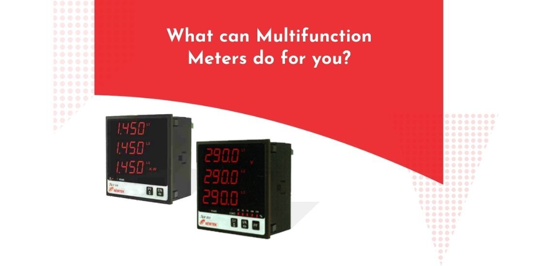
As the name implies, Multifunction meter is a digital meter that measures multiple parameters of a single-phase or a 3-ppthse network and displays at least 3 parameters simultaneously pn its LED or LCD display.
The meter comes in a standard size of 96mm x 96mm Front Fascia. Multifunction meters generally have an optional MODBUS Port (serial communication – RS 485) for data logging to PC or SCADA.
It may also have one or more optional digital output-relays or open collector transistor outputs for alarm or overload protection. The meter is mounted on a panel for users to monitor the measurement. In short, the purpose of the MFM meter is measurement, display, record and control an electrical network.
Parameters measured by a Multifunction Meter
- Basic Parameters: Phase Voltages (VR, VY, VB), Line to Line Voltages (VRY, VYB, VRB), Line currents (IR, IY, IB), Frequency
- Power Parameters: Active Power, Reactive Power, Apparent Power
- Phase Active Powers (P1, P2, P3) and Sum Active Power (SumP, Phase Reactive Powers (Q1, Q2, Q3) and Sum Reactive Power (SumQ), Phase Apparent Powers (S1, S2, S3) and Sum Apparent Power (SumS)
- Power Factor and Phase Angle: Phase-wise and average value
- Demand Measurement: Instantaneous and Maximum Demand measurement
- Current Demand, Max Current Demand, k\W demand (import & Export) & Max kW demand (import & Export) kVA demand (import & Export) & Max kVA demand (import & Export)
- Energy Measurement: Active Energy (kWh), Reactive Energy (kWh), Apparent Energy (kWh)
- Generator Parameters: RPM (revolutions per minute), RUN-Hours (cumulative time the Load was running), ON-Hours (cumulative time the Meter’s auxiliary supply was ON), Number of Interruptions (count that indicates how many times the Aux Supply failed until now), Min and Max Parameters (minimum level and maximum level the parameters attained until now), Average/ System Voltage, Average/System Current
Specifications/terms related to Multifunction Meter
Network type: This is the electrical network where Meter will be installed for measurement of electrical parameters. It could be a 3 phase 4 wire, 3 wire or single phase network.
Input Voltage Range This is the voltage range between which the meter can measure directly. The meter will directly measure the input voltage of an electrical network within this range.
Example: 0….. 290 VLN (0…. 500VLL). To measure input voltage higher than this range, an external Potential Transformer (PT) has to be installed. The PT will scale the voltage down to this range. When an external PT is used along with the meter, then, you need to enter the primary and secondary of this PT into the meter to get the correct readomg of the input voltage.
Input Current Range: This is the range of input current that the meter can measure directly. The meter will directly measure the input current of an electrical network within this range.
Example: 0…. 5A or 0…. 1A. To measure Input current higher than this range, an external Current Transformer (CT) must be installed. The CT will scale it down to this range. When an external CT is used along with the meter then you need to enter the primary of this CT and secondary of this CT into the meter to get the correct reading of the input current
Auxiliary Supply: FTHe meter needs application of power to switch on and function. This is supplied by the Auxiliary supply which has separate termination. Aux supply can be derived from input voltage or could be kept separate. If Aux supply is applied independent of input voltage, the Meter remains ON even when input voltage falls to zero and can continue measurement. Depending on the meter design, the Aux supply could be AC, DC or Universal wide range (ACDC).
Example: AC Aux: 230 V +/- 20% or 110V +/- 20% or DC Aux: 110VDC +/20% Or Universal Aux: 80——300VAC DC
Accuracy Class: This is the figure that indicates the measurement accuracy of the meter. Example Class 1.0 or Class 0.5 or Class 0.2. Closer the value of class approaches 0, more accurate is the meter.
Optional Outputs: These outputs are optional features of the meter and are not available in the standard version of the meter.
MODBUS (RS 485) Communication Port: This optional feature enables the meter to send its data over MODBUS to PC or SCADA for data logging purpose. Through this port, the Meter can be polled by an external software and data can be recorded for further analysis.
Digital Output: These are either potential free relays or open collector transistor outputs for controlling/tripping external circuits, for generating alarm based on an event.
Conclusion
Apart from measuring the basic power consumption, Multifunction Meters also measure some advanced parameters such as Power Factor and Demand. This data can then be used to optimize your power consumption. Thus, MFM meters are a key asset in power saving strategy.

